Start with the mechanical job
Layered prints are often anisotropic: properties can differ along and across layers. If a part carries a recurring load, think about where the load is transferred and whether it risks separating layers. Material, process and printer settings strongly affect this tradeoff.
If a part is purely decorative, visible surface quality and minimized supports may matter more than directional strength. There is no universally optimal orientation.
Look for overhangs and contact area
Overhangs can require support structures, especially if geometry begins with no material underneath. Support material can leave contact marks and consume time. A flat, stable first-layer footprint can simplify adhesion, but the largest footprint is not automatically best for every model.
Examine the slicer’s layer preview and support visualization. Compare candidate orientations rather than deciding from a shaded model alone. The bed-fit calculator checks six axis-aligned bounding-box permutations only; it does not score print quality or support needs.
Test important dimensions
Where a dimension must be accurate, consider whether it will be printed vertically, horizontally or near the bed. First-layer effects and resolution limits can vary by axis. Verify those claims for your specific machine with physical measurements.
Keep the orientation recorded alongside your model version. A tiny orientation change can make an old successful slicing profile a poor fit.
Worked example
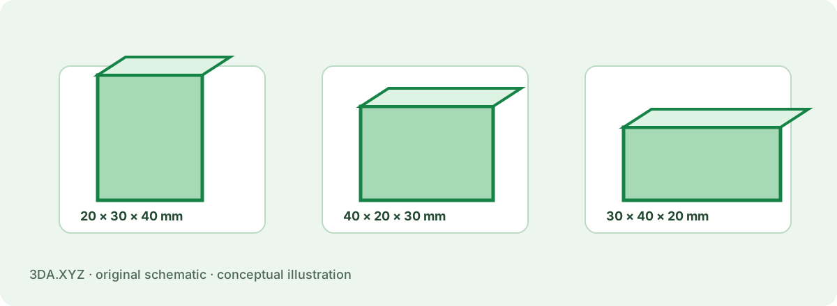
A 20 × 30 × 40 mm block can stand 40 mm tall or lie 20 mm tall. The two orientations share the same volume but present different footprints, heights and layer counts.
Important limitation
Do not infer layer strength from the STL file alone. Mechanical performance depends on the actual printed process, material and settings.
Practical checklist
- What load will this part carry?
- What surfaces matter cosmetically?
- Where will supports touch?
- Is the footprint stable?
- Do supports and brim fit on the bed?
Common questions
Does rotating a mesh change its volume?
A rigid rotation preserves volume; scaling or slicing settings can change actual material use.
Can a part fit geometrically but fail in the slicer?
Yes. Brims, supports, printer exclusions or overhangs can make the choice impractical.
Primary references
External specifications provide format or process context; the examples and calculations here are original 3DA explanations.
A worked example: a wall hook
A hook carries load along its curve. Printed upright, the load pulls layers apart at the bend and it snaps along a layer line. Printed lying on its side, every layer contains the full curve, and it is several times stronger — with a flat face on the bed and few supports. The same reasoning applies to brackets, clips and handles: put the load path inside the layers.
Orientation trade-offs at a glance
| Priority | Orient so that… |
|---|---|
| Strength | Loads run along layers |
| Surface finish | Visible faces are vertical or on top, not on supports |
| Fewest supports | Overhangs stay under ~45° |
| Accuracy of holes | Hole axes are vertical |
| Speed | The part is low and wide rather than tall |