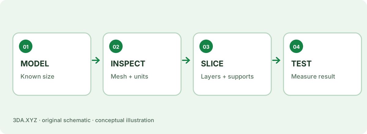
Start with a known solid
For a first experiment, choose a simple box or cylinder with flat surfaces and clearly stated dimensions. A photo, render or screenshot is not automatically a printable surface mesh. The printer or slicer ultimately needs a representation of the shape it should build.
Download the original 20 mm reference cube, or create a box in the 3DA model inspector. Keep track of the model’s intended millimeter dimensions. A 20 mm cube should appear as 20 × 20 × 20 mm in the slicer, not 20 inches or 20 meters.
Validate the file before slicing
Inspect the model’s boundary edges, winding consistency and connected components. A closed, consistently oriented mesh is a useful starting condition for an ordinary solid, but it cannot prove every manufacturing constraint. Extremely thin features, self-intersections and tiny gaps can still cause failures.
STL and OBJ are commonly used for geometry transfer, but they do not impose a universal length unit. The same bare numbers can be interpreted at very different physical sizes. A core 3MF model can declare units explicitly. The importer and slicer remain the final authority for what they actually support.
Slice, inspect and print
In the slicer, choose the actual printer profile, nozzle size and material, then review first-layer adhesion, the layer preview, overhangs, supports and estimated material usage. Geometry that looks correct in a shaded viewport can still produce unwanted isolated lines or unsupported islands in the sliced toolpath.
Start small and observe the first layers. A successful test print provides evidence of your printer, filament and settings together. One good test does not validate every future design, and results will vary with machines and materials.
Record your settings
Keep the model file, chosen orientation, material, layer height, scale, slicer profile and final observations together. This turns a successful print into a repeatable process and makes a failure easier to diagnose.
After printing, measure the part with appropriate tools and compare it with the declared model dimensions. Use that result to calibrate expectations before designing close-fitting parts.
Worked example
A downloaded cube described as 20 mm on each side should read 20 × 20 × 20 mm in the slicer. If it appears as 0.02 mm or 508 mm, stop before printing: the unit interpretation is likely wrong.
Important limitation
Do not assume “watertight” means “print guaranteed.” A watertight mesh can still have inaccessible cavities, thin walls or unsupported geometry.
Practical checklist
- Choose a dimensioned model
- Verify imported scale
- Inspect the sliced layers
- Select a correct printer/material profile
- Print a simple test and measure it
Common questions
Do I need CAD to start?
No. An original sample model is enough to learn the import, slicing and printing workflow.
Does the 3DA viewer send my file to a server?
No. The 3DA.XYZ Studio opens STL, OBJ, PLY, GLB, glTF and 3MF in the browser.
Primary references
External specifications provide format or process context; the examples and calculations here are original 3DA explanations.
Your first week, step by step
- Day 1: level the bed, print the manufacturer’s test model in PLA.
- Day 2: print a calibration piece — our overhang test and a tolerance gauge.
- Day 3: print something useful from the model library — a keychain tag, a cable-friendly spring or a cookie cutter.
- Day 4: make your own: a first model or a gear in the gear generator.
- Day 5: learn the design rules and troubleshooting.
Pick materials with the materials guide and machines with how to choose a 3D printer.