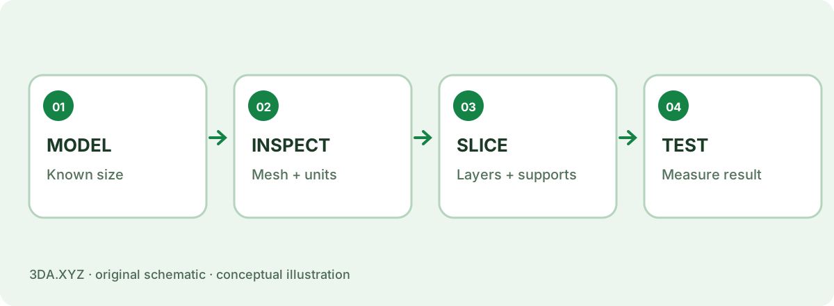
Model to toolpath
The slicer loads geometry, applies its interpretation of units and scale, places the model on a virtual build plate and intersects it with layers. It then plans walls, top/bottom solid regions, infill, travel paths and supports according to its profiles.
The output for many filament printers is a form of G-code or manufacturer-specific machine instructions. Different machines and processes use different command languages and file types; do not assume one output format works for all printers.
Settings change physical usage
Wall count, infill density and support settings change how much material is extruded. Therefore geometric volume is not a reliable substitute for the slicer’s material estimate.
Layer height influences the number of slices and may change surface appearance, duration and mechanical behavior. Material and nozzle settings must match the actual hardware. Use your slicer’s documented presets as a starting point rather than random values from unrelated printers.
Inspect the preview
Look for unexpected gaps in walls, unsupported regions, floating islands and overlong bridges. Check first-layer footprint, supports, purge structures and the final Z height. Verify that the selected profile names your actual printer and material.
The 3DA cost calculator works best after a slicer gives you estimated grams and time. The bed-fit tool is an earlier bounding-box screen, not a replacement for slicer review.
Worked example
Two 20 mm cubes with the same exterior mesh can consume different amounts of filament if one is sliced with solid infill and the other with sparse infill.
Important limitation
A correct-looking preview is a necessary check, but cannot promise adhesion, dimensional accuracy or reliable printing.
Practical checklist
- Confirm printer and material profile
- Check scale
- Set layer and wall parameters
- Review supports and overhangs
- Inspect first and last layers
- Record estimated mass and time
Common questions
Is G-code the same as STL?
No. STL represents surface geometry; G-code or similar printer instructions describe tool actions.
Can the 3DA viewer slice a print?
No. It inspects supported geometry; use a compatible dedicated slicer for toolpath generation.
Primary references
External specifications provide format or process context; the examples and calculations here are original 3DA explanations.
What a slicer changes
| Setting | Effect |
|---|---|
| Layer height | Detail vs time; 0.2 mm is the common default for a 0.4 mm nozzle |
| Walls, top and bottom layers | Strength and finish (guide) |
| Infill % and pattern | Weight, time, stiffness |
| Supports | Which overhangs get held up |
| Temperatures and fan | Material behaviour (materials) |
| Speed and acceleration | Time vs quality and ringing |
| Seam position | Where each layer starts and ends |
The output: G-code
The slicer writes G-code: a list of machine moves such as G1 X50 Y20 E0.8, meaning “move to X50 Y20 while extruding 0.8 mm of filament”. Some printers use variants or binary forms, but the idea is the same.
Preview before printing
Always scrub through the layer preview: look for gaps in walls, floating islands that start in mid-air, and thin features that disappear. A cut in the Studio’s section view is a good mental model of one slice.
Check your understanding
1. What does a slicer produce?
It converts the model into toolpaths.