A model that looks complete in a viewer can still produce an unexpected result in a slicer. The file describes geometry; the printing workflow must also decide how to build that shape with a particular machine and material. Preparing a print means checking both.
This guide focuses on the path from a model to a filament-printing slicer preview. Exact settings depend on your equipment. Use the printer and material maker's instructions for operation; the example checks here are not physical validation of a part.
Start with the intended object
Record the target dimensions and what the part is supposed to do. For a first exercise, use the dimensioned box tutorial or an original sample from the model library. An uncomplicated shape makes it easier to notice scale or orientation problems.
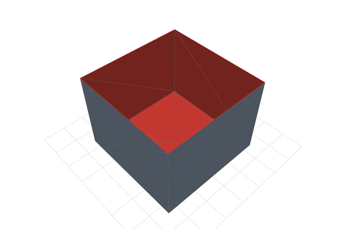
Open the export in the 3DA geometry viewer and inspect it from several directions. Orbit to look for unexpected pieces, then use wireframe to see the surface structure. This is an early visual check. The viewer does not repair meshes, slice layers or establish whether a part will print successfully.
Confirm scale in the slicer
Import the file into the slicer you intend to use. Check the displayed dimensions against your notes. Do this even if the preview looks plausible: a familiar silhouette can hide a large scale error. Rotate the view and confirm which side will sit on the build plate.
Keep the original file and save your slicer project separately. If you resize the model, record the change. Scaling can affect the size of holes, gaps and thin features, so it deserves another review rather than a quick glance at the outside.
Resolve surface problems deliberately
For a conventional solid print, the intended boundary should define a clear enclosed object. Gaps, intersecting surfaces or disconnected fragments can make that intention ambiguous. A slicer may repair some problems automatically, but repair is not guaranteed and can change the result. Prusa's model-repair guidance explains that limitation.
When the slicer shows a warning, inspect what it changed. Compare important openings and small pieces with the source. If the repair closes a hole that was part of your design, return to the modeling application and correct the geometry there. Preserve an unmodified source so you can review the difference.
Choose an orientation for the actual task
Look at the contact area on the bed, the direction of important surfaces and places where new layers would extend beyond material underneath. Orientation can change the need for supports and the finish of visible surfaces. Prusa's design guide discusses overhangs, bridges and support tradeoffs.
A long rectangular block is a useful comparison: preview it on a broad face and then standing on an end. Compare the footprint and the stack of layers. This exercise shows a workflow choice; it does not establish which orientation is best for every part. A functional part may need additional testing for its intended loads and fit.
Inspect the layers, not only the outer shape
Choose a profile for the actual printer, nozzle and material, then slice. Move through the preview from the first layer upward. Check where extrusion paths begin, whether small details appear and whether top surfaces have the intended support beneath them.
Layer height, perimeters and internal fill have different roles. Layer height controls the vertical increments of the build; perimeters form the wall outlines. The Prusa layers-and-perimeters reference explains why changing one setting is not equivalent to changing another. Do not assume a finer layer height restores a feature that is too narrow for the selected extrusion setup.
| Preview check | Question to answer |
|---|---|
| First layer | Is the expected face on the bed, with the intended footprint? |
| Thin details | Do walls, text and small pieces actually generate paths? |
| Openings | Did holes and gaps remain open after import and repair? |
| Supports | Are they present where needed, and can you remove them from the intended surfaces? |
| Final layers | Does the top close as intended rather than ending with missing features? |
Keep a record of the handoff
Save the model, slicer project, profile choice and a short note about orientation. Generate machine instructions for the actual printer only after reviewing the preview. A file prepared for one machine is not automatically suitable for another.
After a real print, compare its measured dimensions and appearance with the target and record any changes before repeating it. Our sample files are geometric learning resources; they carry no claim of demonstrated print strength, fit or material suitability. If you need to change the exchange format first, return to the 3D format guide.